
- 非IC关键词
企业档案
- 相关证件:

- 会员类型:普通会员
- 汪小姐

- 电话:0769-83033107
- 手机:13546962276
- 张先生
- 手机:13712630522
- 地址:东莞市长安镇明和电子广场科楼区F1702
- 传真:0769-83124718
- E-mail:xinhuiic@126.com
产品分类


*现货供应 三*管2*772
NEC/日本电气
2*772
功率
大功率
中频
PNP型
点接触型
硅(Si)
to-126
树脂封装
100(MHz)
4(A)
产品信息
*现货供应 三*管2*772
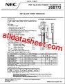
PNP SILICON POWER TRANSISTOR
2*772
PNP SILICON POWER TRANSISTOR
DATA SHEET
Document No. D17118EJ2V0DS00 (2nd edition)
(Previous No. TC-3569)
Date Published March 2004 N CP(K)
Printed in Japan c
The mark shows major revised points.
2004
D*CRIPTION
The 2*772 is PNP silicon transistor suited for the output stage of 3
W audio amplifier, voltage regulator, DC-DC converter and relay
driver.
FEATUR*
• Low saturation voltage
VCE(sat) ≤ −0.5 V (IC = −2 A, IB = −0.2 A)
• Excellent hFE linearity and high hFE
hFE = 60 to 400 (VCE = −2 V, IC = −1 A)
• Less cramping space required due to *all and thin package and
reducing the trouble for attachment to a radiator.
No insulator bushing required.
ABSOLUTE MAXIMUM RATINGS
Maximum Temperature
Storage Temperature −55 to +150°C
Junction Temperature 150°C Maximum
Maximum Power Dissipation
Total Power Dissipation (TA = 25°C) 1.0 W
Total Power Dissipation (TC = 25°C) 10 W
Maximum Voltages and Currents (TA = 25°C)
VCBO Collector to Base Voltage −40 V
VCEO Collector to Emitter Voltage −30 V
VEBO Emitter to Base Voltage −5.0 V
IC(DC) Collector Current (DC) −3.0 A
IC(pulse)
Note Collector Current (pulse) −7.0 A
Note Pulse Test PW ≤ 350 μs, Duty Cycle ≤ 2%
ELE*RICAL CHARA*ERISTICS (TA = 25°C)
CHARA*ERISTIC SY*OL T*T CONDITIONS MIN. TYP. MAX. UNIT
DC Current Gain hFE1 VCE = −2.0 V, IC = −20 mANote 30 220
DC Current Gain hFE2 VCE = −2.0 V, IC = −1.0 mANote0
Gain Bandwidth Product fT VCE = −5.0 V, IC = −0.1 A 80 MHz
Output Capacitance Cob VCB = −10 V, IE = 0, f = 1.0 MHz 55 pF
Collector Cutoff Current ICBO VCB = −30 V, IE = 0 A −1.0 μA
Emitter Cutoff Current IEBO VEB = −3.0 V, IC = 0 A −1.0 μA
Collector Saturation Voltage VCE(sat) IC = −2.0 A, IB = −0.2 ANote −0.3 −0.5 V
Base Saturation Voltage VBE(sat) IC = −2.0 A, IB = −0.2 ANote −1.0 −2.0 V
Note Pulse Test: PW ≤ 350 μs, Duty Cycle ≤ 2%
CLASSIFICATION OF hFE
Rank R Q P E
Range 60 to 120 100 to 200 160 to 320 200 to 400